Содержание
ESP32
ESP32 S2 mini
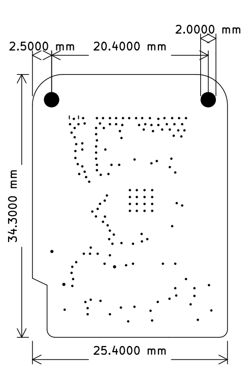
Размеры
Спецификация
based ESP32-S2FN4R2 WIFI IC
- Type-C USB
- 4MB Flash
- 2MB PSRAM
- 27x IO
- ADC, DAC, I2C, SPI, UART, USB OTG
- Compatible with LOLIN D1 mini shields
- Compatible with MicroPython, Arduino, CircuitPython and ESP-IDF
- Default firmware: MicroPython
| Operating Voltage | 3.3V |
| Digital I/O Pins | 27 |
| Clock Speed | 240MHz |
| Flash | 4M Bytes |
| PSRAM | 2M Bytes |
| Size | 34.3*25.4mm |
| Weight | 2.4g |
Распиновка
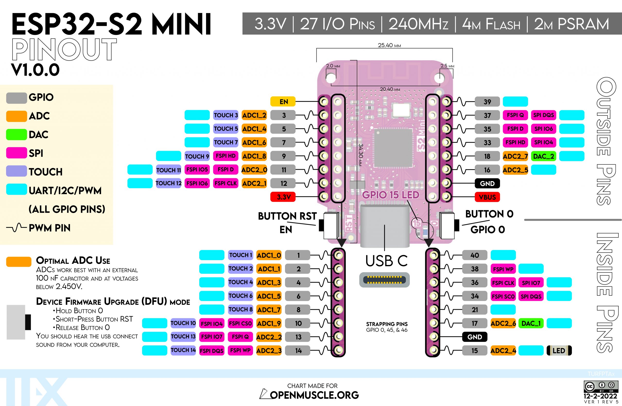
LED - GPIO2
ESP32-wroom-32 30pin
Распиновка

Принципиальная схема

Габаритный чертёж

Прошивка ESPEasy
# Запустить flash_download_tool
# В первой строке выбрать прошивку (bin), установить галочку и адрес смещения установить «0»
# Подключить питание к модулю при нажатой кнопке boot
# Нажать кнопку «START»
# Перезагрузить модуль по питанию
# Подключиться к новой сети WiFi. Пароль по умолчанию «configesp»
# Настроить подключение к сети wifi http://192.168.4.1/config
# Перезагрузить модуль
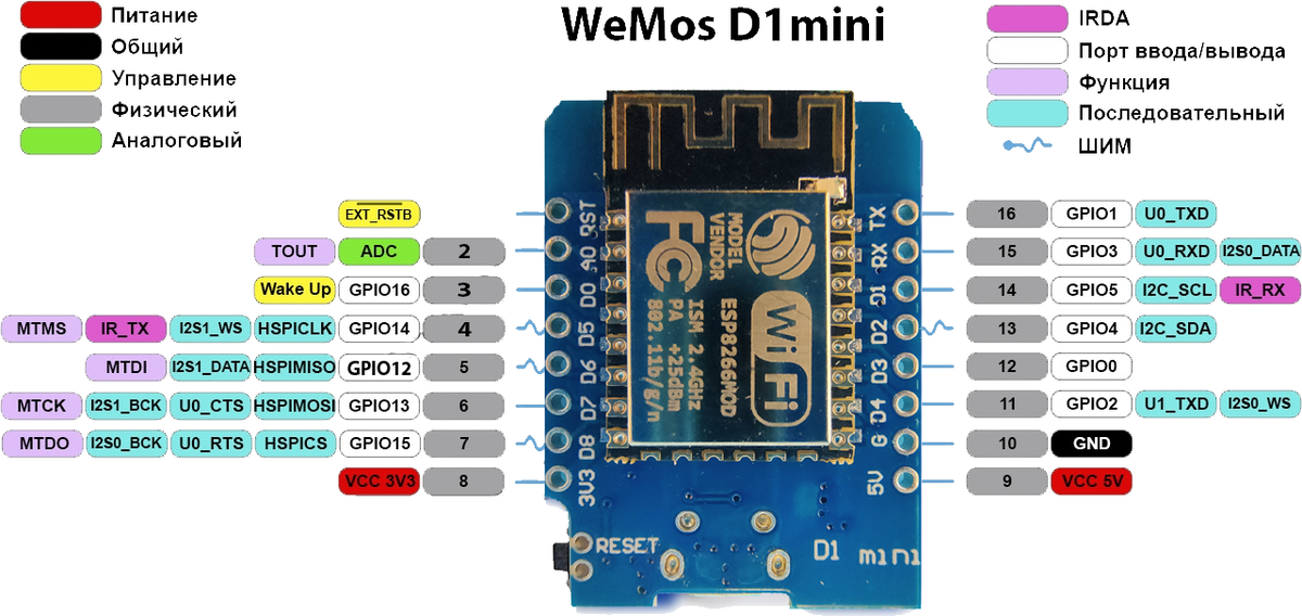
ESP8266
ESP8266 wemos d1 mini
Распиновка
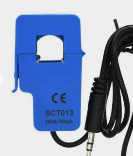
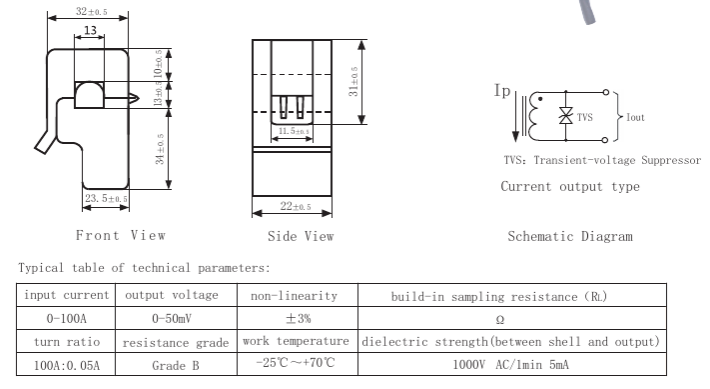
Датчики
Датчик тока sct013
DC UPS Power module
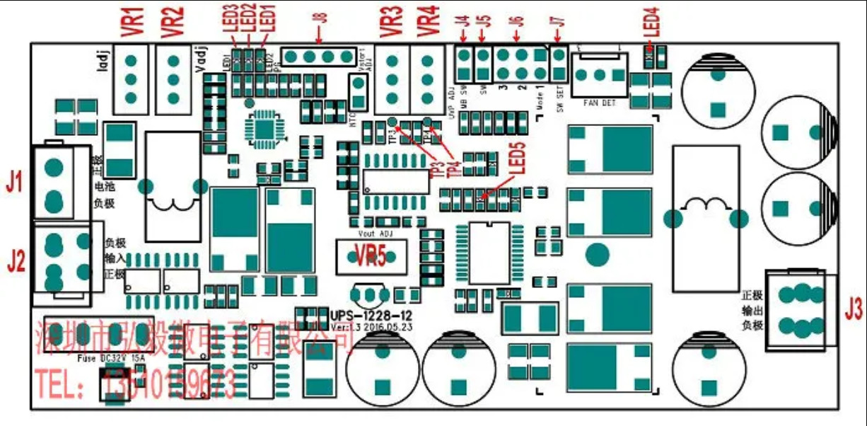
J1: battery interface (battery positive and negative) 5557-2P
J2: Input power interface 5557-4P
J3: Output power interface 5557-4P
J4: Mainboard on/off control output. When used as a backup power supply for the computer, the module can control the mainboard switch through J4, and send instructions to the mainboard to shut down when the battery is undervoltage.
J5, J7:
J7 open circuit: J5 is closed to start the power supply, disconnected to close the power supply, each time the power is turned on, J5 must be disconnected and closed again to turn on the power.
J7 short circuit: J5 is closed to start the power supply, and when it is disconnected, the power supply is turned off. When the power is turned on, the power supply is automatically turned on as long as J5 is closed.
J7 is open by default
Users can choose a suitable starting method according to actual practical requirements
J6: Delay setting jumper (this jumper is only used when the load is the computer motherboard, and it is not set in other situations (ie mode 0)
J8: The external lead-out terminals of LED1-LED3, lead from this socket when external LEDs are required.
VR1: Charging current adjustment potentiometer
VR2: charging voltage adjustment potentiometer
VR3: Battery start threshold voltage adjustment potentiometer (порогового напряжения запуска аккумулятора)
VR4: Battery undervoltage protection threshold voltage adjustment potentiometer (порогового напряжения защиты от пониженного напряжения аккумулятора)
VR5: Output voltage adjustment potentiometer
LED1: Input power indicator, blue. On when the input power is normal
LED2: After the charging is completed, the light is on, red, and it goes out during charging
LED3: This light is on during charging, green, and goes out after charging. When the battery is discharged and the battery voltage drops below the start threshold voltage VSTART, this light flashes. When the battery voltage is lower than the undervoltage protection threshold voltage VUVP, when the power is turned on, the power cannot be started, and the light flashes twice, indicating that the battery is undervoltage.
LED4: Output voltage indicator, red, on when there is output voltage, and off when the output is off Instructions for use
Датчики
Распиновка
Датчики I2C на GX12 4P

1. GND (бело-оранжевый) 2. VCC (оранжевый) 3. SDA (бело-синий) 4. SCL (синий)
Датчики I2C на «SM2.54» 4pin
 Черный - 0
Красный – VCC
Белый - SDA
Желтый - SCL
Черный - 0
Красный – VCC
Белый - SDA
Желтый - SCL
Датчик температуры DS18B20
Jack 3.5

GX12-3p

1. GND 2. DATA 3. VCC